Electric Aluminum Foundry
Greetings again everyone! I know it has been a very long time since I have updated this blog, but please don't think my interest has waned. In fact it has been quite the opposite. The reason I haven't posted in a while is chiefly due to the workload of my Electrical Engineering degree course, which I have now supplemented with an extra Year in Computer Science. Also, I have completed two summer internships at Arm, this summer and last summer, so my time spent in the lab has been sparse. Despite this, I have still managed to work on and complete a multitude of different projects and experiments between my last post and now. The following posts will document what I've got up too during summer and the COVID lockdown.
Back in February last year, I decided to build a metal melting foundry inspired by the plaster of paris + sand + bucket design by The King of Random (RIP). Why you ask? Because if playing with molten metal is as easy as this then wouldn't I! Also, this opens up a new door of metal working, which I will be able to utilize in numerous other projects where wood or plastic won't do.
As you can see from the image, the original design was quite rough around the edges. This was mainly because it was built with friends and we all really wanted to see a soda can melt before the day was out. The Nichrome filament certainly got the can hot, to the point of discoloration, but unfortunately not hot enough to melt it.


If was a good first attempt and we learnt a lot. After that I decided to invest the time and money to build a much better version during April 2019. I decided to go down the refractory brick route, as that would allow the foundry to last many more cycles before eventually breaking. The other crucial difference is the inclusion of a lid. The only way to heat up the crucible to melting temperature's is to build up as much heat as possible and trap it inside with a lid, so none of it could escape out the top. This is something that seems obvious now, but wasn't back in our first build; and it now no surprise that the original design couldn't melt the can.
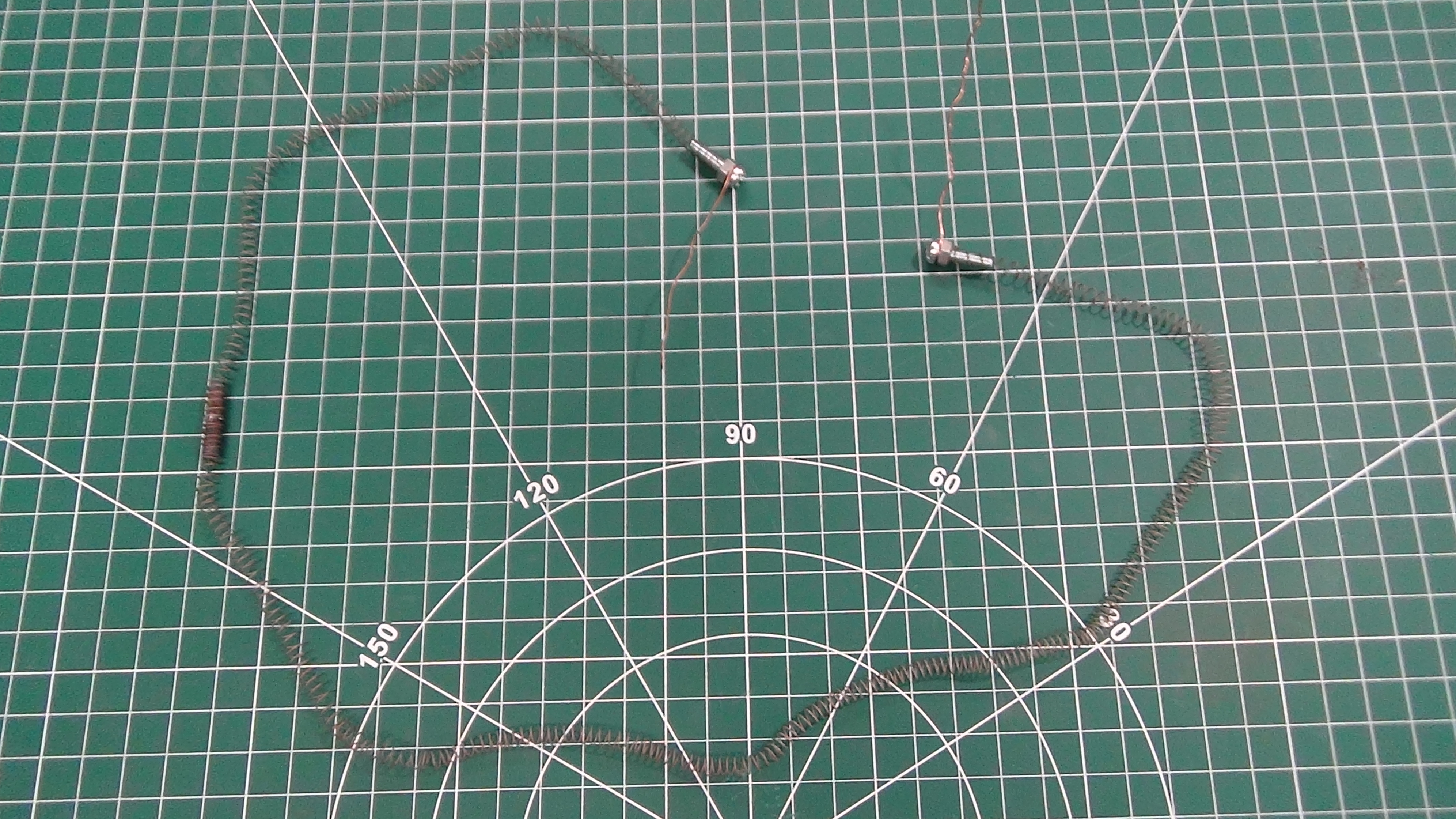
Below you can see the Nichrome heating element connected to a long power cable.

PPE and giant tongs to handle to 800+ degree Celsius environment that will exist inside the foundry.

The refractory bricks were fairly expensive. I will leave you to wonder how much shipping cost :(

I started by lining up the bricks to check sizes. My new massive crucible fits snuggly inside.

It was then time to cut and file down the groves for the heating element to rest. Refractory brick is certainly an interesting ceramic. They can handle extreme compressive forces just like regular bricks, but can be cut through like butter with a saw and very little effort. They definitely go on my list of strange materials I've worked with.


Building something to withstand high temperatures presents many new interesting challenges. For instance, how does one go about attaching the heating element to the foundry wall? You obviously cant use any kind of cable, adhesive or fastener. Its not even safe to use screws as they could even melt. And how do you secure the whole thing together? My initial thoughts were a wooden structure of course, but that's no use since even the outside of the foundry will reach extreme temperatures. A lot of my skills and resources were redundant for this project and I had to resort to alternatives. For mounting the heating element, I simply carved out a grove in the brick all the way around where it will rest undisturbed. As you can see from the image, I lined up the bricks in a set order such that the heating element would spiral up the sides of the foundry and around the crucible in the centre.

Thick bolts and copper wire were used as a pass through from the regular power cable to the heating element.
Before securing the whole thing together, I wanted to do a dry run to ensure that the foundry worked and would melt down cans for real this time. I set up what I had and surrounded it with regular bricks to retain structural integrity.


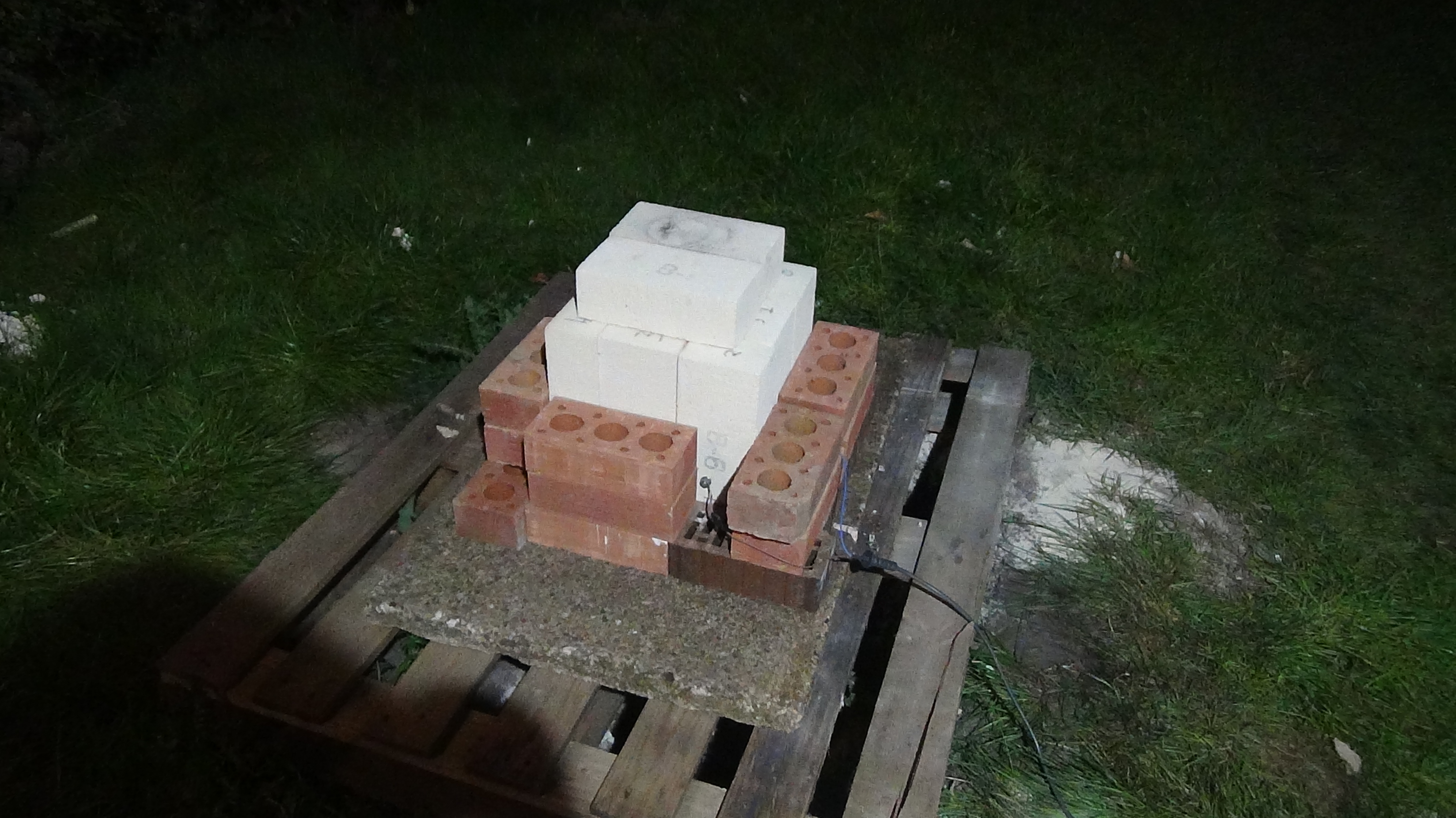

I assembled it during the day and fired it up at night. After a few hours of heating up, I dropped a can inside and watched it liquefy in a puff of smoke. It was truly a satisfying experience, my foundry was finally operational!

However, it would be a long while before I brought out the foundry again. University resumed and my internship away from home occupied most of my summer. The server cabinet project (next post) took up a lot of my time at the end of summer 2019 and the first half of the following year; mainly because eliminating the servers deafening noise was at the top of my to do list in order to make working in the lab bearable. But once that was out of the way and the sun was back out, I spent this summer improving the foundry.
I started by securing the whole thing together using refractory cement and metal cladding.


At this point you may be asking what metal I will actually be melting down with this foundry. Well I have been thinking about that for a while, a year before I even built the foundry in fact. I had known I wanted to build one as soon as I saw TKOR's video showcasing his build many years ago. And so, I started collecting cans from the summer of 2017! I attempted to collect as many as possible by asking my friends and family to contribute to the cause with their cans also. Before long, I bit off perhaps a little more than I could chew, and ended up with enough cans to sink a small ship.


What started with a cardboard box of cans under the desk ended up to almost 10 full bin bags occupying an inconvenient amount of space in the lab. I estimate over a 1000 and more are still being added. Luckily it was time for things to change. I fired up the foundry and began the long task of melting them down.


At first I had some issues with the Nichrome heating element getting too hot and melting itself. I replaced it with a slightly more resilient Kanthal heating element and it worked a treat. The new and improved foundry performed efficiently and consistently for many hours over many weeks.
I started by casting some 'muffins' using a biscuit baking tray. It's incredible how bright these things glow even minutes after being poured from the crucible.


The aluminum muffins were fun to make, but in order to store all that aluminum more effectively I needed to cast an ingot. This process involved a fair bit of work. To cast shapes without using consumable molds, Greensand is used. Greensand is essentially regular sand mixed with Bentonite clay. This make the sand stickier and easier to mold and form shapes. The molten metal is then poured into the sand and takes the shape of the mold.
I whipped up a bit of Greensand and tipped it into a wooden box I created. I then made a mold of an ingot by cutting a block of wood at an angle using my new band saw. Next, I placed the mold into a hole in the sand and pressed the remaining sand around the mold to form the correct shape. I put two screws into the top of my "wooden bar" so that it's easy to pull out of the sand. What was left was a hole exactly the shape of the wooden mold ready for casting.


After a laborious evening melting down can after can, there was eventually enough to cast an ingot! Unfortunately, I didn't leave it long enough to cool before quenching and the ingot broke in half. Not a problem though, I can easily melt it down and recast it. I waited longer with the second one and ended up with a sleek single ingot but forgot to get a picture.


And that's all for now folks. It's going to take me a very long time to melt all these cans down to ingots and I haven't done much more since the summer. The next exciting milestone (and blog post) will be when I cast something actually useful. If you look at the shape of the casting box you will notice its very long and thin. This was deliberate, because my ultimate plan for this project is to make SWORDS! Stay tuned for more updates on this and videos will be coming to the channel soon.


